Fixing laggy SSH connections

This is more of a reminder post as I’m sure I’ll be hitting this problem again and posting about it will help me remember the solution.

So if you’re struggling with a laggy SSH connection to your PI, slow typing, slow output to common commands (like dmesg) and even freezes, try adding these 2 things to your /etc/ssh/sshd_config file:

  1. UseDNS no
  2. IPQoS 0x00

The second one fixed my problem. I have no idea why but after one day of getting frustrated with what seems like it should just work I started trying all suggestions I could find.

I honestly don’t understand how something so basic can fail like this… By basic I mean used by everyone/everything all the time, not simple.


ESP8266 Video Streaming

I just finished the first version of a library + firmware that allows streaming of video data over wifi using packet injection and monitor mode oon the esp8266.

The project is hosted on github:  https://github.com/jeanleflambeur/esp8266_bridge_broadcast

I plan to use it to replace the finicky WN721 wifi cards that I’m using now with something I have more control over.

I’m testing using NodeMCU ESP12F modules and the results are very good.


From the Readme:

This lib + firmware allows you to inject and receive packets using an esp8266 module. It’s meant for streaming data – like video – similarly to the wifibroadcast project, but instead of using of the shelf wifi dongles with patched firmwares, it uses the esp8266.

The advantages over standard wifi dongles (like the WN721N) are:

  • Ability to control the rate (from 1Mbps to 56Mbps) and modulation (CCK with and w/o short preamble and ODFM)
  • Cheaper and readily available
  • Very short stack so less points of failure. It doesn’t have to go through the kernel, 802.11 stack, rate control, firmware etc
  • Easy to add new features in the firmware
  • Very good sensitivity and power: Up to -92dBi and 22.5dBm
  • SPI connection so no USB issues on the Raspberry Pi

Disadvantages:

  • More complicated connectivity. The module is connected through SPI to the host device which is a bit more complicated than just plugging a USB dongle
  • Limited bandwidth. With PIGPIO, 12Mhz SPI speed and 10us delay you can get ~8Mbps throughput. Recommended settings are 10Mhz and 20us delay which results in 5-6Mbps

There are 2 helper classes in the project:

  • A Phy which talks to the esp firmware. It supports:
    • Sending and receiving data packets up to 1376K. Data is sent through the SPI bus in packets of 64 bytes. When receiving you get the RSSI as well, per packet.
    • Changing the power settings, in dBm from 0 to 20.5
    • Changing the rate & modulation. These are the supported ones: 0: 802.11b 1Mbps, CCK modulation 1: 802.11b 2Mbps, CCK modulation 2: 802.11b 2Mbps, Short Preamble, CCK modulation 3: 802.11b 5.5Mbps, CCK modulation 4: 802.11b 5.5Mbps, Short Preamble, CCK modulation 5: 802.11b 11Mbps, CCK modulation 6: 802.11b 11Mbps, Short Preamble, CCK modulation 7: 802.11g 6Mbps, ODFM modulation 8: 802.11g 9Mbps, ODFM modulation 9: 802.11g 12Mbps, ODFM modulation 10: 802.11g 18Mbps, ODFM modulation 11: 802.11g 24Mbps, ODFM modulation 12: 802.11g 36Mbps, ODFM modulation 13: 802.11g 48Mbps, ODFM modulation 13: 802.11g 56Mbps, ODFM modulation
    • Changing the channel.*This is broken for now as the radio doesn’t seem to react to this setting for some reason.
    • Getting stats from the esp module – like data transfered, packets dropped etc.
  • A FEC_Encoder that does… fec encoding. It allows settings as the K & N parameters (up to 16 and 32 respectively), timeout parameters so in case of packet loss the decoder doesn’t get stuck, blocking and non blocking operation.

Both classes can be used independently in other projects.

Test app

There is also a test app (esp8266_app) that uses them and sends whatever is presented in its stdin and outputs to stdout whatever it received. You can configure the fec params, the spi speeds and the phy rates/power/channel.

Firmware

The firmware is done using the Arduino IDE and can be compiled with the 2.3.0 or 2.4.0 sdk. It does require some patching of the Arduino make command to allow access to an internal function: After downloading the board in arduino, go to packages/esp8266/hardware/2.3.0/platform.txt and locate the compiler.c.elf.flags line:

compiler.c.elf.flags={compiler.warning_flags} -O3 -nostdlib -Wl,--no-check-sections -u call_user_start -u _printf_float -u _scanf_float -Wl,-static "-L{compiler.sdk.path}/lib" "-L{compiler.sdk.path}/ld" "-L{compiler.libc.path}/lib" "-T{build.flash_ld}" -Wl,--gc-sections -Wl,-wrap,system_restart_local -Wl,-wrap,spi_flash_read

Then add this at the end of that line: -Wl,-wrap=ppEnqueueRxq

It should read this:

compiler.c.elf.flags={compiler.warning_flags} -O3 -nostdlib -Wl,--no-check-sections -u call_user_start -u _printf_float -u _scanf_float -Wl,-static "-L{compiler.sdk.path}/lib" "-L{compiler.sdk.path}/ld" "-L{compiler.libc.path}/lib" "-T{build.flash_ld}" -Wl,--gc-sections -Wl,-wrap,system_restart_local -Wl,-wrap,spi_flash_read **-Wl,-wrap=ppEnqueueRxq**

Android USB Tethering & Debugging

If you want to debug an Android application that needs USB tethering – say a FPV app – then you can use the following steps.

  1. You need to first connect the device to the same wifi network as your PC.
  2. Then start the USB tethering and provide internet to whatever you need – say a Raspberry PI running wifibroadcast or my RC software.
  3. Run this in a terminal:
    adb connect 192.168.1.33:5555
    where 192.168… is the WiFi IP of your device
  4. That’s it. The device is now visible to Android Studio & QtCreator just like if it were connected by USB. I didn’t notice any slowdowns in deployment vs USB – but my app is rather small (a few MB)


Unbalanced motors, Rate PID & Bandwidth

For a multirotor to fly, the thrust of each motor has to be equal, within certain tolerances. These tolerances depend on the bandwidth of the multirotor which are usually reflected in (well tuned) rate PIDs.

Let me explain:

The rate PIDs are usually tuned to reach the best impulse response which depends on the moment of inertia (radius, mass and mass distribution) and thrust inertia (prop weight, motor power, ESC, etc etc).
Unbalanced motors result in a steady-state error for the rate PID which it has to compensate for using the P and the I terms. Going too high with either term – higher than the multirotor bandwidth can allow – will cause oscillations and instability.


It might seem obvious that unbalanced motors are bad. In the end all motors – even high end ones – tend to have slight Kv differences which results in different thrust for the same PWM input. It happened to me when I last tested my quad – it kept flipping over at launch and I didn’t understand why the PIDs cannot compensate for this. All other quads work and surely they have their own unbalanced motors.

So when I got home I measured the Kv of each motor and I found that one of them is lazier – around 90% thrust compared to the others.

So I fired up the simulator and added some randomness to each motor thrust (between 80% and 120%) and yes – the quad wouldn’t fly. The rate PID was unable to compensate for the difference in thrust. Increasing a lot the P term or a bit the I term stabilized the quad.

So Success!!

But what if I couldn’t increase the P or I because of oscillations? What if my PID was at its limit, stability wise? Then the quad would not be able to fly with this particular combination of motors and moment of inertia.

Seems like a silly conclusion – if the motors are bad the quad will not fly – but I felt like I had some sort of epiphany that the thing responsible to compensate for bad motors is the same thing responsible for fully using the quad bandwidth – so unbalanced motors need some bandwidth margin to allow the PID to compensate for them.


Testing rig

I built a custom testing rig out of some plywood sticks and these kind of elastic cords:

Plastic Coated Spring Hooked Cord (C121)

There is just enough clearance for 7 inch props and the quad is free to rotate around one axis (Y or roll in the video). I can easily change the free axis as the cords connect to the arms with metal hooks.

The issue I’m debugging now is related to a tendency of the motors to generate different thrust for the same throttle input. I think it’s because the ESCs have different settings on them as I couldn’t find any issue with my code so far. If I send 50% throttle to all motors the quad spins a lot.


si4463 FPV #2

In my last post I talked about using the si4463 chip to send video, telemetry and RC data to the quadcopter. I calculated the bandwidth and it seemed that 500kbps video with 5/7 FEC coding should be possible.

I wrote the code, linked everything together and it kind of worked. The video was stable, not many packets lost but the latency was pretty bad. It got up to ~200ms from the current 100-130ms but worse than this, the video was very choppy. I managed to narrow it down to the H264 codec in the raspberry pi: the bitrate you configure in the codec is an average bitrate, per second. Each frame can vary a lot in size as long as the average is preserved (with some allowed over and undershoot). I got I-frames of 12-16KB and P-frames of 400-500 bytes (at 30 FPS). The I-frames took way longer to send than the P-frames and this resulted in a choppy video. I tried to play around with settings – like disabling CABAC and activating CBR but nothing made the bitstream uniform enough.

The final, biggest problem was actually caused by the RF4463F30 module – and it’s the same problem I had months ago when I tried to use them: they introduce a LOT of noise in the power line, enough to cause all the I2C chips on the quad to fail.

I tried all kinds of capacitors to decouple the module and reduced the noise a lot but there seem to always be some capacitive/inductive coupled noise persisting.

In the end I just gave up and went back to the RFM22B chip which just works. For video I went back to the monitor mode/injection system but did change the modulation to CCK, 5.5Mb to hopefully reduce the possibility of interference with other 2.4Ghz RC systems. CCK is spread spectrum similar to DSSS and should be able to coexist with RC systems around.


So yeah, FPV through a very constrained channel with a temperamental H264 encoder and a very temperamental transceiver module is not fun…


si4463 FPV

It’s been a while since my last post and that’s not because I abandoned silkopter, but because I’ve been very busy working on it.

During my latest test 3 weeks ago I noticed that the video link is not as stable as I wanted. I’m using a system similar to wifibroadcast – wifi cards in monitor mode doing packet injection. They are working on 2.4Ghz and the area where I’m flying seems to have this band a bit crowded, causing the video link to be glitchy.

On the other hand my 433Mhz RC link has been pretty solid. So inspired by this I started thinking if I could do the same thing: send video through my RC link.

I already had the RF4463F30 transceivers which are using the si4463 chip and I knew them well (and hated them a lot) so I thought to give it a try.

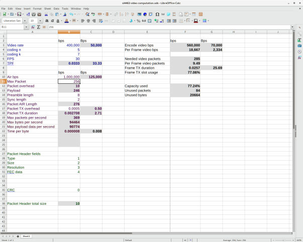
Now – the max bandwidth the si4463 supports is limited to 1mbps which might seem like  enough for 640×480 resolution but there is a lot of overhead that effectively limit this to around 755kbps. Since I want some FEC – say 5/7 coding – I end up with 500kbps target video bitrate.

I made an xls to ease the calculations. It allows me to specify the air bitrate, packet sizes, packet overhead, video bitrate, fps, preamble/sync sized, header sizes etc and calculates all kind of nice info, including if the link is viable or not.

Here is a screenshot with my current calculations:


For the video link, 500kbps seems like enough as there’s not a lot of movement in a quad, specially with a gimbal. To further improve quality and decrease latency I’m experimenting with the x264 software compressor library instead of the GPU compressor in the PI. It seems to be able to compress real-time a 640×480 video with good quality, zero latency setting and 2 cores only.

I still have to compare the quality between the 2 (GPU and x264) though.

GPIO ramp up/down

While testing the menu system yesterday I notice a strange problem. Sometimes pressing  a button triggers not only the GPIO associated with that line, but adjacent lines as well.

My first thought was ‘wiring problem’ as everything is crammed inside the RC with 30+ jumper wires, so I started shaking and moving wires around but it didn’t seem to change much.

Then I turned to code – I thought I might have a bug – and after close introspection the code seemed correct:

  • Set the column GPIO as output
  • Set the column GPIO high (+3.3v)
  • Read all 4 line GPIOs, see which button is pressed
  • Set the column GPIO as input to turn it off
  • Repeat

Everything seemed ok so I took out the oscilloscope and probed one of the columns.

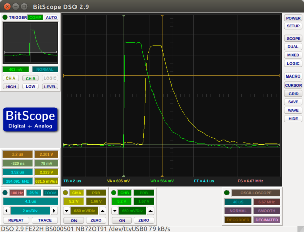
Here’s what I got:

screenshot-from-2016-11-21-09-50-26

I probe 2 column GPIOs here and the trigger is on the green trace. The 2 problems become obvious – first of all the pin goes low too slow so by the time the next pin is high, the previous one still has ~2.3V, enough to register as high. And second – the code lops through this without any delay between pins.

On paper, the code works correctly but not so in real life where there is inductance and bandwidth limits for triggering GPIOs high/low.


The fix is trivial. I changed the loop like this:

  • Set the column GPIO as output
  • Set the column GPIO high
  • Wait 2 microseconds for the pin to settle
  • Read all 4 line GPIOs
  • Set the column GPIO low <— this causes the voltage to drop way quicker than just setting the gpio as input
  • Set the column GPIO as input
  • Wait 2 microseconds for the pin to settle
  • Repeat


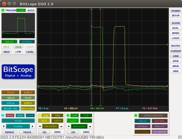
Here’s the trace on the oscilloscope after the changes:

screenshot-from-2016-11-21-10-08-42


As you can see there is a clear, safe distance between triggering adjacent column GPIOs and (not visible in the trace) the lines are sampled right in the middle of the high interval.

This works perfectly now.

RC – First HW Test

After a few more failed attempts to print the RC case with ABS I finally gave PLA a chance. Ordered some black 1.75 filament from amazon and a few days later I printed the case successfully from the first try. PLA is great, it’s easy to print, it smells like sugar when printing – as opposed to the chemical smell of ABS – and the quality is really good. However it doesn’t like to be sanded. At all! It’s like trying to sand rubber – or more accurately – sugar.

I decided to stop worrying about the finish so much and ordered some plastic primer and white matte paint. In the meantime I finished the RC PCB and made all the connections and did the first real test.

Here it is:

Features:

  • 3 axis gimbal for yaw, pitch and roll. It’s a very high quality one with bearings and hall sensors instead of pots
  • Motorized linear pot for the throttle. I went for motorized because when changing flight modes I want to have the throttle in the correct position to avoid stopping the motors
  • 0.96″ OLED screen for status info, calibration and other things
  • 8 ADC channels – 4 for the sticks, 3 for the individual LiPo cells and another one for the Gimbal Pitch pot
  • a 4×4 button matrix implemented with pigpio for all the buttons and switches
  • 2 rotary encoders for live editing of parameters like PIDS, menu navigation, etc
  • 2x 2.4 GHZ wifi diversity for the video feed
  • 5.8 GHZ wifi for the phone connection – to send the video feed through
  • 433 Mhz 30 dBm link for the RC data
  • 2.2Ah 3S LiPo battery for ~5h of continuous use, with charger/balancer port

The screen is connected through i2c1 at 1Mhz together with 2 ADC sensors (ADS1115).
I’m using this library to talk to the screen but noticed that a full display update takes ~20-30ms during which I cannot talk to the ADC sensors. To fix this, I changed the library and implemented partial screen updates. Now I can call screen->displayIncremental(1000) and the class will send incremental lines to the screen for 1000 microseconds (1 millisecond). The overall FPS is the same as with full updates but I get to do other things while the display is being updated. To avoid tearing I also added double buffering to the class and an explicit swap method.

The end result is a 40-45 screen updates per second but each update is split in 12-13 partial uploads with ADC readings in the middle. So I can sample the ADC at ~600Hz which is more than enough for a RC system.

The RC has 13 buttons and 2 rotary encoders requiring a total of 17 GPIO. Since I didn’t have enough I ended up grouping the 13 buttons in a matrix of 4×4 following this tutorial. This allows me to reduce the number of GPIO to 12 (8 for the matrix and 4 for the rotary encoders). I implemented the matrix reading using PIGPIO and added some debounce code to avoid detecting ghost presses/releases. Seems to work great and it’s very fast.


Most of the HW is done and it’s a mess of wires. I’m working now on some videos of potting it together, making the connections and the calibration.

The next step is to work on the phone app to receive the video feed, although I think I will give the quad a test – line of sight.

I really want to fly soon.

RC Almost Finished

Here’s the case after my best attempt:


It looks… bad. The paint coat is horrible and full of scratches and the screen is too big.

But worst of all, the screen is not bright enough in direct sunlight. Not even close. I don’t have a photo but after brief testing I’d say it’s unusable.

So I’m pretty disappointing with the result – I ended up with a big, heavy RC system that is too dim to be usable for FPV.

I searched for a week for alternative capacitive touch screens, preferable in the 5-7 inches range but found nothing bright enough under 100 euros.

So after a mild diy depression I got an idea that will solve at lease 3 of the issues – cost, bright screen and the RC size: use my Galaxy Note4 phone as the screen.

The setup will look like this:

  • The quad will send video through 2.4Ghz, packet injection (a.k.a. wifibroadcast method) and RC stream through 433Mhz
  • The RC will receive both video and RC data and relay them to the phone using another 5.8Ghz wifi UDP connection. The phone will decompress the H264 video using OMX (or whatever is available) and display it with telemetry on top.
  • The phone will also act like a touchscreen interface to control the RC/Quad


Basically this is what most commercial quads (like Mavic) are doing. I’m sure the video link is 2.4GHz due to longer range than 5.8 and better penetration and the connection with the phone is done over a 5.8, low power link.


So the next steps are:

  • Redesign a smaller case that will accomodate a Raspberry Pi 3, the RC stick and fader + buttons and wifi cards
  • Write a quick android application that can connect to the RC and decompress the video stream
  • Profit!