Category Archives: GS

RC – First HW Test

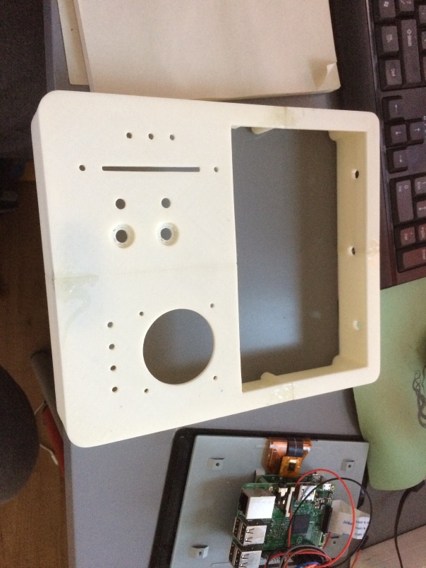
After a few more failed attempts to print the RC case with ABS I finally gave PLA a chance. Ordered some black 1.75 filament from amazon and a few days later I printed the case successfully from the first try. PLA is great, it’s easy to print, it smells like sugar when printing – as opposed to the chemical smell of ABS – and the quality is really good. However it doesn’t like to be sanded. At all! It’s like trying to sand rubber – or more accurately – sugar.

I decided to stop worrying about the finish so much and ordered some plastic primer and white matte paint. In the meantime I finished the RC PCB and made all the connections and did the first real test.

Here it is:

Features:

  • 3 axis gimbal for yaw, pitch and roll. It’s a very high quality one with bearings and hall sensors instead of pots
  • Motorized linear pot for the throttle. I went for motorized because when changing flight modes I want to have the throttle in the correct position to avoid stopping the motors
  • 0.96″ OLED screen for status info, calibration and other things
  • 8 ADC channels – 4 for the sticks, 3 for the individual LiPo cells and another one for the Gimbal Pitch pot
  • a 4×4 button matrix implemented with pigpio for all the buttons and switches
  • 2 rotary encoders for live editing of parameters like PIDS, menu navigation, etc
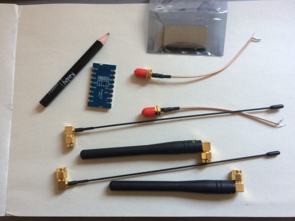
  • 2x 2.4 GHZ wifi diversity for the video feed
  • 5.8 GHZ wifi for the phone connection – to send the video feed through
  • 433 Mhz 30 dBm link for the RC data
  • 2.2Ah 3S LiPo battery for ~5h of continuous use, with charger/balancer port

The screen is connected through i2c1 at 1Mhz together with 2 ADC sensors (ADS1115).
I’m using this library to talk to the screen but noticed that a full display update takes ~20-30ms during which I cannot talk to the ADC sensors. To fix this, I changed the library and implemented partial screen updates. Now I can call screen->displayIncremental(1000) and the class will send incremental lines to the screen for 1000 microseconds (1 millisecond). The overall FPS is the same as with full updates but I get to do other things while the display is being updated. To avoid tearing I also added double buffering to the class and an explicit swap method.

The end result is a 40-45 screen updates per second but each update is split in 12-13 partial uploads with ADC readings in the middle. So I can sample the ADC at ~600Hz which is more than enough for a RC system.

The RC has 13 buttons and 2 rotary encoders requiring a total of 17 GPIO. Since I didn’t have enough I ended up grouping the 13 buttons in a matrix of 4×4 following this tutorial. This allows me to reduce the number of GPIO to 12 (8 for the matrix and 4 for the rotary encoders). I implemented the matrix reading using PIGPIO and added some debounce code to avoid detecting ghost presses/releases. Seems to work great and it’s very fast.


Most of the HW is done and it’s a mess of wires. I’m working now on some videos of potting it together, making the connections and the calibration.

The next step is to work on the phone app to receive the video feed, although I think I will give the quad a test – line of sight.

I really want to fly soon.

RC Almost Finished

Here’s the case after my best attempt:


It looks… bad. The paint coat is horrible and full of scratches and the screen is too big.

But worst of all, the screen is not bright enough in direct sunlight. Not even close. I don’t have a photo but after brief testing I’d say it’s unusable.

So I’m pretty disappointing with the result – I ended up with a big, heavy RC system that is too dim to be usable for FPV.

I searched for a week for alternative capacitive touch screens, preferable in the 5-7 inches range but found nothing bright enough under 100 euros.

So after a mild diy depression I got an idea that will solve at lease 3 of the issues – cost, bright screen and the RC size: use my Galaxy Note4 phone as the screen.

The setup will look like this:

  • The quad will send video through 2.4Ghz, packet injection (a.k.a. wifibroadcast method) and RC stream through 433Mhz
  • The RC will receive both video and RC data and relay them to the phone using another 5.8Ghz wifi UDP connection. The phone will decompress the H264 video using OMX (or whatever is available) and display it with telemetry on top.
  • The phone will also act like a touchscreen interface to control the RC/Quad


Basically this is what most commercial quads (like Mavic) are doing. I’m sure the video link is 2.4GHz due to longer range than 5.8 and better penetration and the connection with the phone is done over a 5.8, low power link.


So the next steps are:

  • Redesign a smaller case that will accomodate a Raspberry Pi 3, the RC stick and fader + buttons and wifi cards
  • Write a quick android application that can connect to the RC and decompress the video stream
  • Profit!

RC Case

I finished designing the case that will fit the silkopter RC system.

Here’s how it looks like:


Components:

  1. Raspberry Pi3
  2. Official Raspberry Pi 7″ touchscreen
  3. A 3 axis gimbal stick for the yaw/pitch/roll
  4. A ADS1115 ADC to sample the sticks and the throttle fader
  5. A motorized 10K fader for the throttle
  6. A brushed Pololu motor controller. Pololu modules are awesome btw
  7. 2 clickable rotary encoders to tune custom parameters like PIDS
  8. 2 switches to save/restore the custom parameters
  9. 7 push buttons to change flight modes, RTH and other cool things


The case is pretty big due to the screen. It’s 22.3 cm tall, 19.5 cm wide and 4.4 cm deep – so I couldn’t print it in one piece on my Prusa I3 printer. So I had to split in in a few pieces, print each one and them glue them together.

After a few failed prints, here’s the end result:

img_0742


I’m painting it now with matte black paint and tomorrow I will put all the components together.

The only problem I’m having now is that I broke my touchscreen while fitting it in the case so I need to order another one.


Binary Releases

I decided to start making binary releases available for everyone to download.

Here’s the first one – the GS and the brain binaries:

https://bintray.com/jeanleflambeur/silkopter/gs_brain/d779ff73ee330c82acc82171ddfdbb03701da784

I’ll write a new post later today or tomorrow about the install steps and how to get it working.

Note this is not finishes for flying, it’s an experimental release of the new version of Silkopter that can be used to debug sensors and test most of the nodes.


Classic TX

I thought to give my Flysky TH9x TX a change to use it with silkopter so I made a new node called “CPPM Receiver”. This samples a CPPM stream on a GPIO and outputs the PWM streams that can be fed into the main node.


It uses the PIGPIO setAlertFunc which calls a user provided function for all level transitions on a certain gpio pin. The resolution is 5 microseconds which is waay more than needed for a standard CPPM stream. The gap between channels is 400 microseconds so way bigger than the minimum resolution of the library.


It started more of a proof of concept but in the end I think it’s perfectly usable.

Here’s a video with it in action, connected to a D8R-II receiver:


RF Modules

I found and bought the RF modules I needed for the GS-brain comms: the RF4463F30

They have a 1W PA, the receiver has -122dBm sensitivity at low data rates and around -90-96dBm at 1Mbps max rate.

They are pretty small and light – under 2-3 grams I think.

IMG_0265

I managed to find a lot of documentation from SI and the RF chip works pretty differently than the RFM22B. It’s not programmed using registers but with SPI commands. You basically create API calls in a uint8_t buffer and send it through SPI.

The FIFO is only 64 bytes but it does have a CRC and a custom 4 byte header to pack various things – like a request id.

So far it seems very nice, I will try to make it work during the weekend.


The plan I have is to use the wifi only for video data – tx only, and the RF4463 for bidirectional commands (GS->Brain and back) and video packet confirmations.

This should allow me to use better the limited wifi bandwidth by using uni-directional comms – so the back packets don’t keep the channel busy – and also have a rock solid link for control.

I did some tests with the RFM22B at 0dBm and it can easily go through 4-5 walls and 20 meters  inside my house. With 20 or even 30dBm I should be able to have a solid 10Km link line of sight.


Definition Language

aaand it’s done!

The definition language for specifying node configuration is finished – at least in principle.

It ended up being a stand-alone library called def_lang (uninspired, I know)

Basically I can now define things like this:

namespace silk
{
  alias mass_t = ufloat;

  struct UAV_Config_Base
  {
    string name : [ui_name = "Name"];
    mass_t mass : [ui_name = "Mass (Kg)"];
    ufloat moment_of_inertia : [ui_name = "Moment Of Inertia"];
  };

  struct Multirotor_Config : public UAV_Config_Base
  {
    struct Motor
    {
      math::vec3f position;
      direction_t thrust_vector = {0.f, 0.f, 1.f};
      bool clockwise = false;
    };

    ufloat radius = 1.f; //m
    ufloat height = 1.f; //m
    ufloat motor_z_torque = 0.f; //Nm
    ufloat motor_thrust = 1.f; //N
    ufloat motor_acceleration = 10.f; //N/s
    ufloat motor_deceleration = 10.f; //N/s
    vector<Motor> motors;
  };
}

And use this definition in 2 possible ways:

    • Dynamically, through a type system:
ts::ast::Builder builder;

auto parse_result = builder.parse_file("definition_file.def");
if (parse_result != ts::success)
{
  std::cerr << parse_result.error().what();
  return;
}

//walk and display the AST
std::cout << builder.get_ast_root_node().to_string(0, true) << std::endl;

ts::Type_System ts;
ts.populate_builtin_types(); //this adds standard built-in types like float and double

auto compile_result = builder.compile(ts); //populate the typesystem from the AST
if (compile_result != ts::success)
{
  std::cerr << compile_result.error().what();
  return;
}

//now the type system is fully populated and all the types is it are instantiable
std::shared_ptr<ts::IStruct_Type> base_type = ts.find_specialized_symbol_by_path<ts::IStruct_Type>("silk::UAV_Config_Base");
std::shared_ptr<ts::IStruct_Type> type = ts.find_specialized_symbol_by_path<ts::IStruct_Type>("silk::Multirotor_Config");

assert(base_type->is_base_of(*type)); //inheritance is respected

std::shared_ptr<ts::IStruct_Value> multirotor_config_value = type->create_specialized_value(); //create a value of type Multirotor_Config
auto construct_result = multirotor_config_value->construct(); //construct it. This struct is default constructible. An alternative is to initialize it using an initializer list

//let's get (select) some members
//the full dot sintax is supported when selecting so things like motors[0].position works
std::shared_ptr<ts::IString_Value> name_value = multirotor_config_value->select_specialized<ts::IString_Value>("name");

//all setters might fail so I need to check the return value
auto result = name_value->set_value("silkopter");
TS_ASSERT(result == ts::success);

//values are serializable as well to an intermediary tree
auto serialize_result = multirotor_config_value->serialize();
TS_ASSERT(serialize_result == ts::success);

//the intermediary tree can be serialized to json or binary
std::string json = ts::serialization::to_json(serialize_result.payload(), true);

//a more complicated example:
//get the motors vector
std::shared_ptr<ts::IVector_Value> motors_vector_value = multirotor_config_value->select_specialized<ts::IVector_Value>("motors");

//create a new motor
std::shared_ptr<ts::IStruct_Value> motor_value = ts.create_value<ts::IStruct_Type>("silk::Multirotor_Config::Motor");

//change it's position
motor_value->select_specialized<ts::IVec3f_Value>("position")->set_value(ts::vec3f(0, 1, 0));

//add it to the vector
auto result = motors_vector_value->insert_value(0, motor_value);
assert(result == ts::success);

Basically  it’s a full type system implementation similar to the C++ one with type safety, templated types, aliases, values, casting, inheritance etc etc. But on top of the standard C++ features it also allows custom attributes on members and types (like ui_name for example), it supports reflection so everything can be enumerated and it’s serializable. This dynamic one will be used in the GS to generate UI for all the nodes. Like this the GS can work with new nodes without me having to do custom UI for each node I intend to add (or everytime I change the node config to add/remove a parameter, or change a type etc)


  • Statically through generated C++ code

From the definition above I can also generate C++ code for all the structs and work with them through getters and setters. Each type in the type system can be mapped to a native C++ type. So in this example, the above structure would be usable like this from generated code:

assert(std::is_base_of<silk::UAV_Config_Base, silk::Multirotor_Config>::value); //inheritance is respected

//create a value of type Multirotor_Config. This also default constructs it
silk::Multirotor_Config multirotor_config_value;

//all members have setters and getters generated for them
std::string name_value = multirotor_config_value.get_name();
multirotor_config.set_value("silkopter");

//values are serializable as well to an intermediary tree
auto serialize_result = silk::serialize(multirotor_config_value); //serialization methods are generated as well
TS_ASSERT(serialize_result == ts::success);

//the intermediary tree can be serialized to json or binary
std::string json = ts::serialization::to_json(serialize_result.payload(), true);

//a more complicated example:
//get the motors vector
std::vector<silk::Multirotor_Config::Motor> motors_vector_value = multirotor_config_value.get_motors();

//create a new motor
silk::Multirotor_Config::Motor motor_value;

//change it's position
motor_value.set_position(ts::vec3f(0, 1, 0));

//add it to the vector
motors_vector_value.insert(motors_vector_value.begin(), motor_value);

//set it back in the config
multirotor_config_value.set_motors(motors_vector_value);

The generated code is simpler to work with partly because it’s a lower level of abstraction (I use the build-in C++ typesystem and work in value space) but also because it’s familiar.

The interested thing is that the generated code keeps inside as a string the definition file contents that it was generated from. This is useful to implement the following flow:

  1. I write the definition file for the bran and all its nodes
  2. I generate the c++ code for the brain. Now all the nodes can use C++ structs for the parameters and config structs. Simple and type-safe as it’s impossible to access non-existing fields or use them with the wrong type. It’s standard, simple C++ structs
  3. When the brain connects to the GS, it sends the def file it was generated from
  4. The GS instantiates a dynamic Typesystem and parses the def file from the brain, so now it will understand and be able to (de)serialize the data it will receive from the brain – like node configs, etc

If I want to add a new node, I add in the def, regenerate the code and use the resulting config struct in the new node. The GS will automatically know how to handle the new node as it will receive the def for it next time it connects to the brain


Easy peasy

Node Definition

As I mentioned in my previous post I’m designing a domain specific language to define the node properties. So far it looks like this:

import "UAV_Config.def"

namespace silk
{

struct Multirotor_Config : public UAV_Config
{
    struct Motor
    {
        vec3f position = {0, 0, 0};
        bool clockwise = false;
    };

    string name;
    float mass = 1.f : [ ui_name = "Mass (Kg)", min = 0.f ];
    float height = 0.5f : [ ui_name = "Height (m)", min = 0.f ];
    float radius = 0.5f : [ ui_name = "Radius (m)", min = 0.f ];
    float motor_thrust = 1.f : [ ui_name = "Motor Thrust (N)", min = 0.f ];
    float motor_z_thrust = 1.f : [ ui_name = "Motor Z Torque (Nm)", min = 0.f ];
    float motor_acceleration = 10.f : [ ui_name = "Motor Acceleration (N/s)", min = 0.f ];
    float motor_deceleration = 10.f : [ ui_name = "Motor Deceleration (N/s)", min = 0.f ];
    vector<Motor> motors : [ ui_name = "Motors" ];
}

}

It looks a lot like C++ but allows some extra attributes on types and members, like ui_name to have a nicer name displayed in the editor, a min/max value for numeric types, the number of decimals for floating points etc.

The grammar is done with flex/bison and it will actually be a full typesystem that I will use to generate serialization/deserialization code offline and to create UIs online in the GS.

The language will support:

  • namespaces, needed to be able to generate the code in the correct namespace in C++ and to separate the types properly
  • basic types, like ints, floats but also uint8_t and friends
  • structs and classes together with inheritance.
  • templated types like vectors.
  • math types like vec2/3/4, quat and matrices
  • initializer lists for vec3/4 etc
  • custom attributes
  • imports

The compiler will take a file and output a typesystem that contains all the types defined in the file. These types will have reflection so they can be traversed. From this typesystem I can generate the C++ code for the brain – the serialization/deserialization to binary and json – and I can generate UI widgets in the GS as well.

I’m still struggling with the grammar definition but over this weekend I will get it done.

I have to admit – doing a domain specific language and a typesystem is actually very satisfying and challenging. I wish C++ would help a bit more with common things like reflection and such. I even considered moving everything to rust or go but then I’ll have another problem – QT and other library bindings…


Node properties

One of the nice things about silkopter is that is very easy to add new types of nodes to the system.

A node can be anything from a sensor to a low pass filter to a PWM generator like PIGPIO. All nodes have the following properties:

  • Zero or more input streams. Each stream has a type and a rate
  • Zero or more output streams. Same as the inputs, they have a type and rate
  • An Init_Params struct that decides the initialization params of the node. Once the node is created this cannot be changed. The usual params that go in this struct is the rate (process frequency), number of channels for a PWM sink etc.
  • A Config struct that holds changable configuration. This can be changed at any time and contains PID settings for example

The Init_Params and the Config structs are custom, per node. They have to be serializable to json for loading/saving, serializable to binary for comms (the json serialization can be used here) and they need to be editable in an UI for the Ground Station

Silkopter defines the Init_Params and Comms in a json file – one per node – and then generates the actual C++ structs and serialization code from this json description. The UI for editing is dynamic, based on the serialized json of the structs.

So for example the load flow is this:

  • the settings.json file is loaded and converted to a json structure using the rapidjson library
  • the list of nodes is iterated and nodes are created from it
  • each node has its init method called with the init_params json passed to it
  • the init method deserializes the init_params json using generated code into a Init_Params C++ struct

The save flow is the inverse of the one above.

Sending the node Init_Params and the Config to the GS and editing it:

  • The get_init_params (or get_config) is called for a node. This serializes the internal Init_Params or Config to json using the generated code
  • The json stringified using rapidjson and sent to the GS
  • The GS parses the string using rapidjson back into a json data structure
  • A QT item model is used over this json to populate a tree view with the data
  • When data is changed by QT as a response to user interaction (typing a new value for example) the json changes. As a result of this its serialized back to string, sent to the Brain which then calls set_config with the json.

So in order to add a new node, 3 steps have to be done – all of them in the brain. The GS is unchanged:

  1. Create the node C++ class with all the processing needed
  2. Create a json description of the Init_Params and Config and generate the code for them using autojsoncxx library
[
    {
        "definition" : true,
        "namespace" : "sz::ADC_Ammeter",
        "name": "Init_Params",
        "members":
        [
            ["uint32_t", "rate", {"required": true, "json_key" : "Rate (Hz)", "default" : 0}]
        ]
    },
    {
        "definition" : true,
        "namespace" : "sz::ADC_Ammeter",
        "name": "Config",
        "members":
        [
            ["float", "scale", {"required": false, "json_key" : "Scale", "default" : 1}],
            ["float", "bias", {"required": false, "json_key" : "Bias", "default" : 0}]
        ]
    }
]

3. Register the new node in the UAV node factory:

m_node_factory.add<ADC_Ammeter>("ADC Ammeter", *this);


The big advantage of having the serialization code generated is that it’s impossible to make mistakes.

The nice thing about having the UI generated is that the GS doesn’t have to change every time a new node is added or a new property is added/removed from an existing node config or init params.


So in the new GS I intend to keep this but I really want to get rid of the json definition file and replace it with a domain specific language. Main reason is that the json is not as expressive as I want and doesn’t support all the attributes I need – like ranges for the values.

I already started working on a flex/bison grammar for this and a library that will handle the reflection.

More details and a working example soon.

New GS

In the past week I started working on the new Ground Station. The problems I’m trying to fix are:

  1. I want a dedicated GS, not a laptop. For this purpose I’m trying a raspberry pi with a 7 inch display (the official RPI touchscreen display), together with a custom case, 2 RC sticks and various buttons. The reason is that a laptop is unwieldy, not bright enough in direct sunlight, tends to get busy with other tasks in the worst moments, doesn’t have a touchscreen (at least my current laptop doesn’t)
  2. I want a nicer interface that focuses on the main purpose of the GS – flying. The current one focuses more on editing the nodes of the quad.

So I started a new project, the GS2 using QT’s QML and a touch driven UI. So far so good, here are some screenshots:


The resolution is 800×480, a bit small TBH but enough for now. The display size is 7″.

So far the experience in QML is great, it takes very little time to build a nice, functional UI. It does require to build proxies for anything that has to be exposed from the C++ side to qml but that’s a good thing as it separates the UI from the logic.

The main things that I still have to figure out are:

  1. How to create a property sheet in QML. This is used to show the init params and configuration for nodes. This UI is generated in the current GS so there is no need to write custom UI for every node but just a description of the parameters in a json file.
  2. How to write the node editor in QML. Screen real-estate is limited and the node structure can get complex. One possible solution is to allow node groups. Basically take the IMU and low pass filters ang build a meta-node – a Filtered IMU – and treat that as a new node in the UI. Or group all the Navio sensors together in a new Navio Node and avoid all the current clutter. This is an interesting feature that deserves a few weekends.


The physical part of the GS – the case, sticks, buttons are still to be designed but I’m sure I can come up with something in a few weekends. The main parts will be:

  • A raspberry pi to drive the display and run the actual GS
  • An AVR to read the sticks, battery voltage and buttons. Could be replaced with another multichannel ADC and the RPI GPIO
  • A few analog sticks. I’m thinking to salvage the ones in my TH9x remote or buy a few of these or these
  • A RFM22B and 2 TL-WN722 wifi cards for the comms. This will be in a detachable module in the GS, connected by a usb cable so I can mount it higher or on top of my car.
  • LEDs, piezo speaker etc

I already have the rpi + display and the first version of the GS working, check out the video here:


All in all – a few months of work. I hope I don’t get demotivated.