While testing the menu system yesterday I notice a strange problem. Sometimes pressing a button triggers not only the GPIO associated with that line, but adjacent lines as well.
My first thought was ‘wiring problem’ as everything is crammed inside the RC with 30+ jumper wires, so I started shaking and moving wires around but it didn’t seem to change much.
Then I turned to code – I thought I might have a bug – and after close introspection the code seemed correct:
- Set the column GPIO as output
- Set the column GPIO high (+3.3v)
- Read all 4 line GPIOs, see which button is pressed
- Set the column GPIO as input to turn it off
- Repeat
Everything seemed ok so I took out the oscilloscope and probed one of the columns.
Here’s what I got:
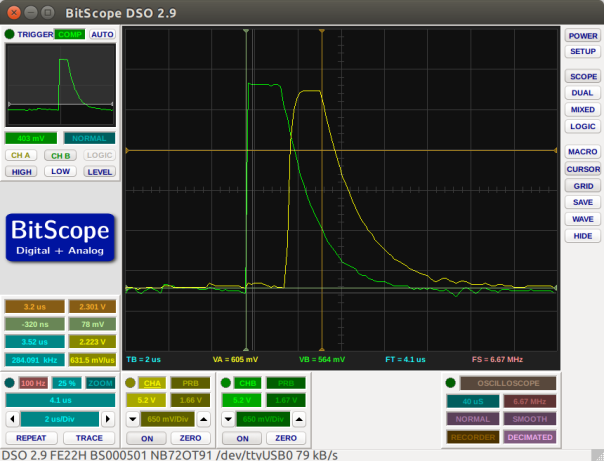
I probe 2 column GPIOs here and the trigger is on the green trace. The 2 problems become obvious – first of all the pin goes low too slow so by the time the next pin is high, the previous one still has ~2.3V, enough to register as high. And second – the code lops through this without any delay between pins.
On paper, the code works correctly but not so in real life where there is inductance and bandwidth limits for triggering GPIOs high/low.
The fix is trivial. I changed the loop like this:
- Set the column GPIO as output
- Set the column GPIO high
- Wait 2 microseconds for the pin to settle
- Read all 4 line GPIOs
- Set the column GPIO low <— this causes the voltage to drop way quicker than just setting the gpio as input
- Set the column GPIO as input
- Wait 2 microseconds for the pin to settle
- Repeat
Here’s the trace on the oscilloscope after the changes:
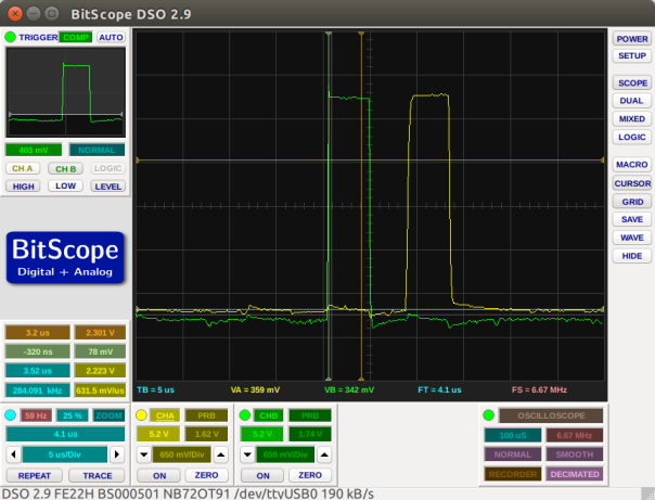
As you can see there is a clear, safe distance between triggering adjacent column GPIOs and (not visible in the trace) the lines are sampled right in the middle of the high interval.
This works perfectly now.
