I finally found a way to use the 5T619 and the camera at the same time. It involves some hacking but it’s relatively simple and non-intrusive.
As you can see in my previous post the problem is that the PMC chip is connected to GPIO 0/1 – same as the camera. So we cannot use them at the same time.
The fix involves the following steps:
1. Redirecting the i2c pins from the camera connector towards i2c-1 on GPIO 2/3 (the user i2c bus)
2. Telling the GPU to use the i2c-1 bus on the new pins
3. Moving all my other i2c stuff from bus 1 which is now being used by the camera to bus 0 where the PMC is
4. Kernel config
5. Usage
There is one small complication though: i2c-0 will become the new user bus and it’s shared with the PMC. The PMC is on GPIO 0/1 and the user-accessible pins are GPIO 28/29. To use each pair, it has to be first switched to ALT0 mode. There are some simple solutions to this and some more complicated ones.
So on with the changes.
Disclaimer: Do this at your own risk.
1. First expose the i2c pins from the camera ribbon cable. These are pins 2 & 3, and since pin 1 (3v3) would be very difficult to insert in the connector on its own – I redirect it as well. You can find the pinout here.

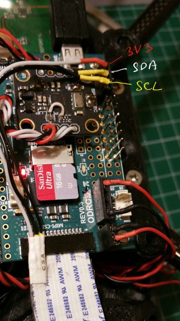
There are 3 wires from the camera cable – 3v3, SDA, SCL – going to 3v3, GPIO 2 and GPIO 3 on the odroid.
You need to solder some wires to these, long enough to reach the 3v3 and GPIOs on the odroid. To do that first carefully cut with scissors the 3 leftmost wires for about 1.5 cm. Then with a sharp blade scratch until you get to the metal part – but carefully not to cut it. Then simply apply some tin with the soldering iron and the rest of the plastic will shrink nicely – exposing more of metal bits. Use shrinkwrap to properly insulate the connection and apply some tape on the whole ribbon cable to strengthen it:

Connect the 3 wires to 3v3, SDA to GPIO2 and SCL to GPIO3:
2. Download the dt-blob.dts file from here and in the pins_rev2/pin_config/pin_defines section, do the following changes:
pin_define@CAMERA_0_I2C_PORT {

type = "internal";

number = <1>; //was 0 before

};

pin_define@CAMERA_0_SDA_PIN {

type = "internal";

number = <2>;//was 0 before

};

pin_define@CAMERA_0_SCL_PIN {

type = "internal";

number = <3>;//was 1 before

};
You can download my modified file from pastebin if you are lazy in a hurry.
Follow this guide to compile this file into a binary blob on the odroid.
3. If you had something connected to i2c-1, connected it to i2c-0 on GPIO 28/29 pins. These are on the opposite side of the odroid as you can see here:

4. Kernel config
By default raspbian only shows i2c-1 in /dev/. Since now we’ll use i2c-0 as the user buss we need to expose it.
To do that, add the bcm2708.vc_i2c_override=1 parameter to /boot/cmdline.txt but _not as the last parameter_.
Reboot and you should have both i2c-0 and i2c-1 available.
5. Reboot and try raspivid -t 0 to check if the camera works. If it says that the camera is not found, there’s something wrong with your i2c connection or the dts. Check both.
If there is no error but you get no image there is something wrong with the ribbon cable. Reattach it, make sure it is properly in.
The tricky part is using the ADC.
For using the odroid 5t619 modules:
If you use the odroid drivers make sure you change GPIO0/1 to ALT0 either from the dts or manually with wirringPi:
gpio mode 17 ALT0

gpio mode 18 ALT0
You could also fix them to change their mode for every access and recompile and redeploy on the odroid. The code is there already – just call the bcm2708_i2c_init_pinmode defined in the i2c-bcm2708 module (after you make it non-static) before accessing the bus. This is pretty involved though and requires a lot of testing so I would go for the dts/manual solution.
From C/C++:
You can do this using the excellent PIGPIO library :
 set_mode(0, PI_ALT0);

set_mode(1, PI_ALT0);
If you want to use some other i2c device attached to the GPIO28/29 pins you have to make sure to first change their mode to ALT0:
//put 0/1 back to input to avoid having 2 sets of pins attached to the same bus (not sure if needed!)

set_mode(0, PI_INPUT);

set_mode(1, PI_INPUT);

//redirect i2c-0 to GPIO 28/29

set_mode(28, PI_ALT0);

set_mode(29, PI_ALT0);
In my case I use a stock raspbian kernel and use both the PMC and the IMU (and soon the SRF02) from C++. So I manually redirect i2c between the 0/1 and 28/29 GPIOs as I need to.
So far this works ok.
Good luck and let me know in the comments if you have any issues.


