Category Archives: Video

ESP8266 Video Streaming

I just finished the first version of a library + firmware that allows streaming of video data over wifi using packet injection and monitor mode oon the esp8266.

The project is hosted on github:  https://github.com/jeanleflambeur/esp8266_bridge_broadcast

I plan to use it to replace the finicky WN721 wifi cards that I’m using now with something I have more control over.

I’m testing using NodeMCU ESP12F modules and the results are very good.


From the Readme:

This lib + firmware allows you to inject and receive packets using an esp8266 module. It’s meant for streaming data – like video – similarly to the wifibroadcast project, but instead of using of the shelf wifi dongles with patched firmwares, it uses the esp8266.

The advantages over standard wifi dongles (like the WN721N) are:

  • Ability to control the rate (from 1Mbps to 56Mbps) and modulation (CCK with and w/o short preamble and ODFM)
  • Cheaper and readily available
  • Very short stack so less points of failure. It doesn’t have to go through the kernel, 802.11 stack, rate control, firmware etc
  • Easy to add new features in the firmware
  • Very good sensitivity and power: Up to -92dBi and 22.5dBm
  • SPI connection so no USB issues on the Raspberry Pi

Disadvantages:

  • More complicated connectivity. The module is connected through SPI to the host device which is a bit more complicated than just plugging a USB dongle
  • Limited bandwidth. With PIGPIO, 12Mhz SPI speed and 10us delay you can get ~8Mbps throughput. Recommended settings are 10Mhz and 20us delay which results in 5-6Mbps

There are 2 helper classes in the project:

  • A Phy which talks to the esp firmware. It supports:
    • Sending and receiving data packets up to 1376K. Data is sent through the SPI bus in packets of 64 bytes. When receiving you get the RSSI as well, per packet.
    • Changing the power settings, in dBm from 0 to 20.5
    • Changing the rate & modulation. These are the supported ones: 0: 802.11b 1Mbps, CCK modulation 1: 802.11b 2Mbps, CCK modulation 2: 802.11b 2Mbps, Short Preamble, CCK modulation 3: 802.11b 5.5Mbps, CCK modulation 4: 802.11b 5.5Mbps, Short Preamble, CCK modulation 5: 802.11b 11Mbps, CCK modulation 6: 802.11b 11Mbps, Short Preamble, CCK modulation 7: 802.11g 6Mbps, ODFM modulation 8: 802.11g 9Mbps, ODFM modulation 9: 802.11g 12Mbps, ODFM modulation 10: 802.11g 18Mbps, ODFM modulation 11: 802.11g 24Mbps, ODFM modulation 12: 802.11g 36Mbps, ODFM modulation 13: 802.11g 48Mbps, ODFM modulation 13: 802.11g 56Mbps, ODFM modulation
    • Changing the channel.*This is broken for now as the radio doesn’t seem to react to this setting for some reason.
    • Getting stats from the esp module – like data transfered, packets dropped etc.
  • A FEC_Encoder that does… fec encoding. It allows settings as the K & N parameters (up to 16 and 32 respectively), timeout parameters so in case of packet loss the decoder doesn’t get stuck, blocking and non blocking operation.

Both classes can be used independently in other projects.

Test app

There is also a test app (esp8266_app) that uses them and sends whatever is presented in its stdin and outputs to stdout whatever it received. You can configure the fec params, the spi speeds and the phy rates/power/channel.

Firmware

The firmware is done using the Arduino IDE and can be compiled with the 2.3.0 or 2.4.0 sdk. It does require some patching of the Arduino make command to allow access to an internal function: After downloading the board in arduino, go to packages/esp8266/hardware/2.3.0/platform.txt and locate the compiler.c.elf.flags line:

compiler.c.elf.flags={compiler.warning_flags} -O3 -nostdlib -Wl,--no-check-sections -u call_user_start -u _printf_float -u _scanf_float -Wl,-static "-L{compiler.sdk.path}/lib" "-L{compiler.sdk.path}/ld" "-L{compiler.libc.path}/lib" "-T{build.flash_ld}" -Wl,--gc-sections -Wl,-wrap,system_restart_local -Wl,-wrap,spi_flash_read

Then add this at the end of that line: -Wl,-wrap=ppEnqueueRxq

It should read this:

compiler.c.elf.flags={compiler.warning_flags} -O3 -nostdlib -Wl,--no-check-sections -u call_user_start -u _printf_float -u _scanf_float -Wl,-static "-L{compiler.sdk.path}/lib" "-L{compiler.sdk.path}/ld" "-L{compiler.libc.path}/lib" "-T{build.flash_ld}" -Wl,--gc-sections -Wl,-wrap,system_restart_local -Wl,-wrap,spi_flash_read **-Wl,-wrap=ppEnqueueRxq**

si4463 FPV #2

In my last post I talked about using the si4463 chip to send video, telemetry and RC data to the quadcopter. I calculated the bandwidth and it seemed that 500kbps video with 5/7 FEC coding should be possible.

I wrote the code, linked everything together and it kind of worked. The video was stable, not many packets lost but the latency was pretty bad. It got up to ~200ms from the current 100-130ms but worse than this, the video was very choppy. I managed to narrow it down to the H264 codec in the raspberry pi: the bitrate you configure in the codec is an average bitrate, per second. Each frame can vary a lot in size as long as the average is preserved (with some allowed over and undershoot). I got I-frames of 12-16KB and P-frames of 400-500 bytes (at 30 FPS). The I-frames took way longer to send than the P-frames and this resulted in a choppy video. I tried to play around with settings – like disabling CABAC and activating CBR but nothing made the bitstream uniform enough.

The final, biggest problem was actually caused by the RF4463F30 module – and it’s the same problem I had months ago when I tried to use them: they introduce a LOT of noise in the power line, enough to cause all the I2C chips on the quad to fail.

I tried all kinds of capacitors to decouple the module and reduced the noise a lot but there seem to always be some capacitive/inductive coupled noise persisting.

In the end I just gave up and went back to the RFM22B chip which just works. For video I went back to the monitor mode/injection system but did change the modulation to CCK, 5.5Mb to hopefully reduce the possibility of interference with other 2.4Ghz RC systems. CCK is spread spectrum similar to DSSS and should be able to coexist with RC systems around.


So yeah, FPV through a very constrained channel with a temperamental H264 encoder and a very temperamental transceiver module is not fun…


RC – First HW Test

After a few more failed attempts to print the RC case with ABS I finally gave PLA a chance. Ordered some black 1.75 filament from amazon and a few days later I printed the case successfully from the first try. PLA is great, it’s easy to print, it smells like sugar when printing – as opposed to the chemical smell of ABS – and the quality is really good. However it doesn’t like to be sanded. At all! It’s like trying to sand rubber – or more accurately – sugar.

I decided to stop worrying about the finish so much and ordered some plastic primer and white matte paint. In the meantime I finished the RC PCB and made all the connections and did the first real test.

Here it is:

Features:

  • 3 axis gimbal for yaw, pitch and roll. It’s a very high quality one with bearings and hall sensors instead of pots
  • Motorized linear pot for the throttle. I went for motorized because when changing flight modes I want to have the throttle in the correct position to avoid stopping the motors
  • 0.96″ OLED screen for status info, calibration and other things
  • 8 ADC channels – 4 for the sticks, 3 for the individual LiPo cells and another one for the Gimbal Pitch pot
  • a 4×4 button matrix implemented with pigpio for all the buttons and switches
  • 2 rotary encoders for live editing of parameters like PIDS, menu navigation, etc
  • 2x 2.4 GHZ wifi diversity for the video feed
  • 5.8 GHZ wifi for the phone connection – to send the video feed through
  • 433 Mhz 30 dBm link for the RC data
  • 2.2Ah 3S LiPo battery for ~5h of continuous use, with charger/balancer port

The screen is connected through i2c1 at 1Mhz together with 2 ADC sensors (ADS1115).
I’m using this library to talk to the screen but noticed that a full display update takes ~20-30ms during which I cannot talk to the ADC sensors. To fix this, I changed the library and implemented partial screen updates. Now I can call screen->displayIncremental(1000) and the class will send incremental lines to the screen for 1000 microseconds (1 millisecond). The overall FPS is the same as with full updates but I get to do other things while the display is being updated. To avoid tearing I also added double buffering to the class and an explicit swap method.

The end result is a 40-45 screen updates per second but each update is split in 12-13 partial uploads with ADC readings in the middle. So I can sample the ADC at ~600Hz which is more than enough for a RC system.

The RC has 13 buttons and 2 rotary encoders requiring a total of 17 GPIO. Since I didn’t have enough I ended up grouping the 13 buttons in a matrix of 4×4 following this tutorial. This allows me to reduce the number of GPIO to 12 (8 for the matrix and 4 for the rotary encoders). I implemented the matrix reading using PIGPIO and added some debounce code to avoid detecting ghost presses/releases. Seems to work great and it’s very fast.


Most of the HW is done and it’s a mess of wires. I’m working now on some videos of potting it together, making the connections and the calibration.

The next step is to work on the phone app to receive the video feed, although I think I will give the quad a test – line of sight.

I really want to fly soon.

RC Almost Finished

Here’s the case after my best attempt:


It looks… bad. The paint coat is horrible and full of scratches and the screen is too big.

But worst of all, the screen is not bright enough in direct sunlight. Not even close. I don’t have a photo but after brief testing I’d say it’s unusable.

So I’m pretty disappointing with the result – I ended up with a big, heavy RC system that is too dim to be usable for FPV.

I searched for a week for alternative capacitive touch screens, preferable in the 5-7 inches range but found nothing bright enough under 100 euros.

So after a mild diy depression I got an idea that will solve at lease 3 of the issues – cost, bright screen and the RC size: use my Galaxy Note4 phone as the screen.

The setup will look like this:

  • The quad will send video through 2.4Ghz, packet injection (a.k.a. wifibroadcast method) and RC stream through 433Mhz
  • The RC will receive both video and RC data and relay them to the phone using another 5.8Ghz wifi UDP connection. The phone will decompress the H264 video using OMX (or whatever is available) and display it with telemetry on top.
  • The phone will also act like a touchscreen interface to control the RC/Quad


Basically this is what most commercial quads (like Mavic) are doing. I’m sure the video link is 2.4GHz due to longer range than 5.8 and better penetration and the connection with the phone is done over a 5.8, low power link.


So the next steps are:

  • Redesign a smaller case that will accomodate a Raspberry Pi 3, the RC stick and fader + buttons and wifi cards
  • Write a quick android application that can connect to the RC and decompress the video stream
  • Profit!

RC Case

I finished designing the case that will fit the silkopter RC system.

Here’s how it looks like:


Components:

  1. Raspberry Pi3
  2. Official Raspberry Pi 7″ touchscreen
  3. A 3 axis gimbal stick for the yaw/pitch/roll
  4. A ADS1115 ADC to sample the sticks and the throttle fader
  5. A motorized 10K fader for the throttle
  6. A brushed Pololu motor controller. Pololu modules are awesome btw
  7. 2 clickable rotary encoders to tune custom parameters like PIDS
  8. 2 switches to save/restore the custom parameters
  9. 7 push buttons to change flight modes, RTH and other cool things


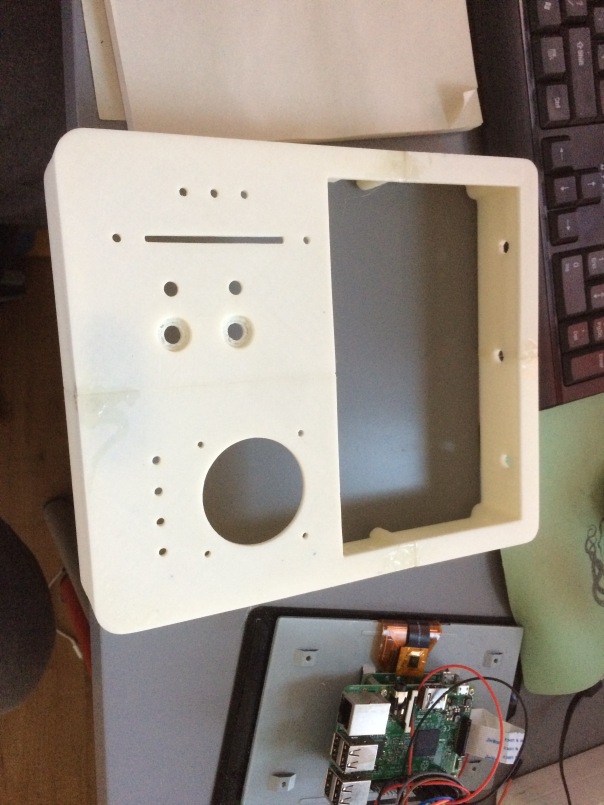
The case is pretty big due to the screen. It’s 22.3 cm tall, 19.5 cm wide and 4.4 cm deep – so I couldn’t print it in one piece on my Prusa I3 printer. So I had to split in in a few pieces, print each one and them glue them together.

After a few failed prints, here’s the end result:

img_0742


I’m painting it now with matte black paint and tomorrow I will put all the components together.

The only problem I’m having now is that I broke my touchscreen while fitting it in the case so I need to order another one.


Gimbal

I ordered these motors and the GLB Mini STorM32 BGC gimbal controller some time ago to make a gimbal for the Raspberry Pi camera. This weekend I managed to model, print and test it.

It weights ~65 grams, is very compact and fits perfectly on my new quad (more on this some other time).

Here’s a timelapse video of the modelling process:

And here’s a video with me mounting it:

And finally the gimbal working:


It works on 6-8.4V (2S), and is very quick to print.

The total cost is ~50e for the controller and motors. In the future I’ll model some extra motor mounts for some more micro gimbal motors.


The STL + Design Spark files will be very soon on github.

[Edit] The files are available here:

https://github.com/jeanleflambeur/silkopter/tree/master/printing/gimbal

Raspberry Pi Camera V2 & GPS

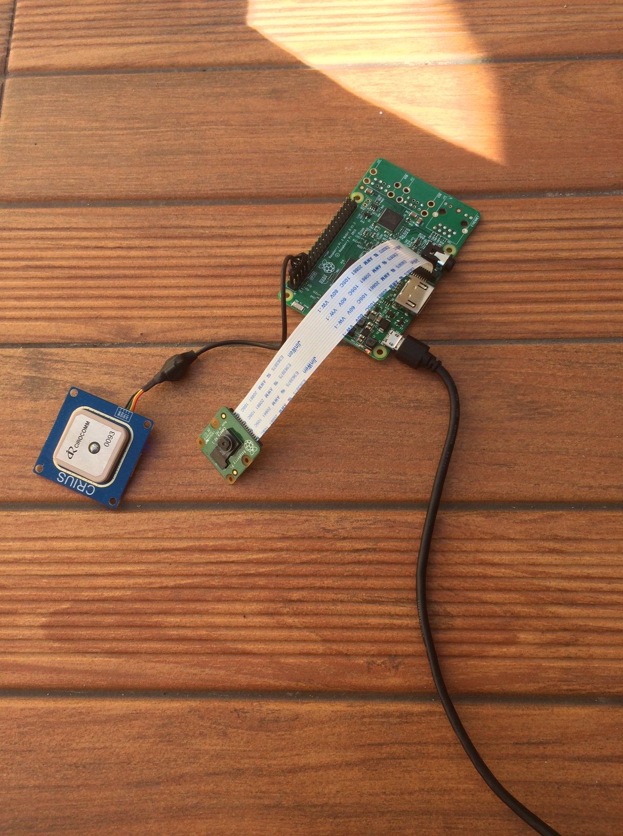
Last weekend I did some tests with a UBLOX Neo6 GPS running next to the V2 camera to see if it’s better than the V1 camera.

The GPS had a clear view of half of the sky with a building to one side so not necessarily ideal conditions. The GPS was powered from the Pi with the cable wrapped through a small ferrite bead.

Here is a picture of the setup:

IMG_0384.JPG

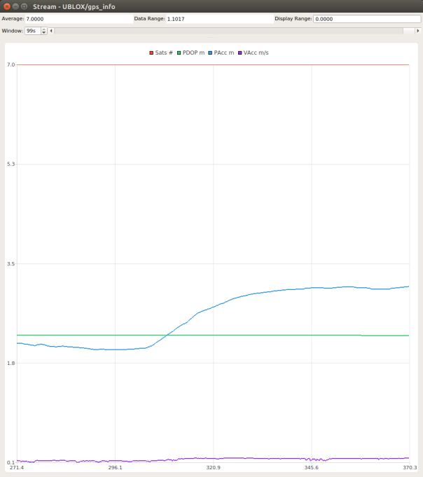
Here is the graph showing the Satelite number, PDOP, Position accuracy and velocity accuracy reported by the GPS:

Screenshot from 2016-07-17 11-16-49.png

There is a clear jump when turning on the camera where PAcc goes from ~2 to ~3.2. With the V1 camera this jumped to 30-40.

The jamming indicator showed 15-20% regardless if the camera was off or on. With V1 the indicator jumped to 100% when turning the camera on.

The number of satellites is the same, as is the PDOP and VAcc.


The spectrum measured with the SDR was crystal clear even when the antenna was almost touching the camera ribbon cable – which btw is unshielded.


So my conclusion is that the V2 interferes with the GPS way less than the V1 and with a bit of (optional) ribbon cable shielding it should be ok for a multirotor.


New GS

In the past week I started working on the new Ground Station. The problems I’m trying to fix are:

  1. I want a dedicated GS, not a laptop. For this purpose I’m trying a raspberry pi with a 7 inch display (the official RPI touchscreen display), together with a custom case, 2 RC sticks and various buttons. The reason is that a laptop is unwieldy, not bright enough in direct sunlight, tends to get busy with other tasks in the worst moments, doesn’t have a touchscreen (at least my current laptop doesn’t)
  2. I want a nicer interface that focuses on the main purpose of the GS – flying. The current one focuses more on editing the nodes of the quad.

So I started a new project, the GS2 using QT’s QML and a touch driven UI. So far so good, here are some screenshots:


The resolution is 800×480, a bit small TBH but enough for now. The display size is 7″.

So far the experience in QML is great, it takes very little time to build a nice, functional UI. It does require to build proxies for anything that has to be exposed from the C++ side to qml but that’s a good thing as it separates the UI from the logic.

The main things that I still have to figure out are:

  1. How to create a property sheet in QML. This is used to show the init params and configuration for nodes. This UI is generated in the current GS so there is no need to write custom UI for every node but just a description of the parameters in a json file.
  2. How to write the node editor in QML. Screen real-estate is limited and the node structure can get complex. One possible solution is to allow node groups. Basically take the IMU and low pass filters ang build a meta-node – a Filtered IMU – and treat that as a new node in the UI. Or group all the Navio sensors together in a new Navio Node and avoid all the current clutter. This is an interesting feature that deserves a few weekends.


The physical part of the GS – the case, sticks, buttons are still to be designed but I’m sure I can come up with something in a few weekends. The main parts will be:

  • A raspberry pi to drive the display and run the actual GS
  • An AVR to read the sticks, battery voltage and buttons. Could be replaced with another multichannel ADC and the RPI GPIO
  • A few analog sticks. I’m thinking to salvage the ones in my TH9x remote or buy a few of these or these
  • A RFM22B and 2 TL-WN722 wifi cards for the comms. This will be in a detachable module in the GS, connected by a usb cable so I can mount it higher or on top of my car.
  • LEDs, piezo speaker etc

I already have the rpi + display and the first version of the GS working, check out the video here:


All in all – a few months of work. I hope I don’t get demotivated.


Comms, revisited

After the latest incident and the loss of my quad it became clear that I need reliability. So far I focused on physical reliability – if the quad is sturdy enough to take a light crash, if it’s well balanced, etc. But I kind of ignored the other 2 aspects – software and comms. Well – not ignored, more like I hoped for the best.

So the next issues to fix are:

  1. Solid comms for the commands (RC) and telemetry. The RFM22B is the perfect candidate for this:
    1. It’s lightweight and small.
    2. Very sensitive receiver (-104dbm @125Kbps)
    3. Powerful TX amp @20dbm
    4. 64byte FIFO so I can drive it directly from the raspberry pi
    5. SPI interface, which the RPI has enough
    6. Good penetration due to the low frequency (433Mhz)

With this setup I should have 5-10Km range, way more than the WIFI video like allows.
The issue will be the comms protocol as the device is half-duplex and the bandwidth is not that much. I made a quick calculation and it should take around 5ms to send an entire 64byte message. With a simple protocol where the GS is the master and the quad the slave, I can allocate 5ms slots to each in turn. This will give me a symmetric 7Kbyte bandwidth, -protocol losses lets say a 5Kbyte bandwidth per second. Should be enough for control and telemetry data.

2. Solid software, especially the GS. I intend to get a RPI3 and display and build a dedicated GS to replace my laptop. For now I will keep my PS4 controller but in the future I will aim to build an entire RC system with integrated touchscreen around the RPI.

I want to run the RPI without an X server and for this I will need a QT version that supports this. Don’t know if it’s possible though.
If this fails, I’ll stop using QT and do all the rendering and UI using something else but this will be quite painful… I’m used to QT and despite all it’s quirks it’s very powerful when doing quick UI work.


What I do know that works in the current setup is:

  1. The RPI2 is powerful enough to handle a quad with WIFI video streaming. It was using ~16-20% CPU at any moment with around 5 threads so no issues here
  2. The case I designed is very sturdy. It’s a combination of 10mm carbon fiber tubes for the arms and ABS plastic for everything else.
  3. Flight time with the current weight of 650grams is around 20-25 min with a 3000mAh multistar LiHV battery. Enough time to enjoy the landscape
  4. The motors + ESC pair are a nice match. RcTimer 1806 1450Kv and RTFQ 4-in-1 12A ESC seem to handle the load nicely. A bit underpowered due to the props – 7×2.4inches but I plan to move to 8×4.5 for the next quad.


So back to the drawing board for a while.


Crash

I took the quad for a spin yesterday and figured out 4 things:

  1. It flew, quite good. Very stable, video quality was good and the signal was very strong even 4-500 meters away
  2. I crashed a few times. See video here: https://www.youtube.com/watch?v=AjwiUQltHaE&feature=youtu.be
  3. Flight time was around 20-25 min with a 3000mAh Multistar LiHV battery. Average amps for hover was around 6-7 which is great. AUW around 630g
  4. Eventually it flew away in a near-by forest and I couldn’t find it. The reason was a sudden loss of signal which triggered the fail safe routine. The quad started climbing to 50m, went home and then dropped to 5m. Problem was that ‘home’ was a few hundred meters into the near-by forest due GPS interference from the camera….

So it’s gone, have to build another one.

The lesson here is that I have some software issues to iron out and that I really need another signal path for the control. I plan to use a rfm22b for this.

The material loss is not that huge – a raspberry pi, 4 rctimer 1806 motors, a brand new battery and a Navio board. A total of 250 euros plus about 2 weeks of work to print all the pieces, etc.


So the next one will need to fix these issues:

  1. Rock solid RC link for control
  2. Solid software without glitches. My GS crashed once in mid-flight (see video) due to the h264 decoder
  3. More portable GS. A laptop with 2 wifi cards, a ps4 controller and many wires is not a fun way to go to the field and fly
  4. The raspicam interferes with the GPSsomething fierce. Even after copper shielding the H Acc went from 2m to 50m after starting the camera…